THE BLACK RIVER VALLEY MODEL RAILROAD WEBSITE
HOW DID YOU DO THAT?
On this page I post small 'how to' articles from time to time. They will consist of text and photo sequences illustrating how I did a specific project on the Black River Valley Railroad. I receive E-mail from site visitors and post photographs and answer/ask questions on several Model Railroading Forums. The E-mails and postings have resulted in questions about how I worked around a problem or accomplished a task on my layout. Whenever I think the solutions may have wide interest, I will endeavor to answer those questions here.
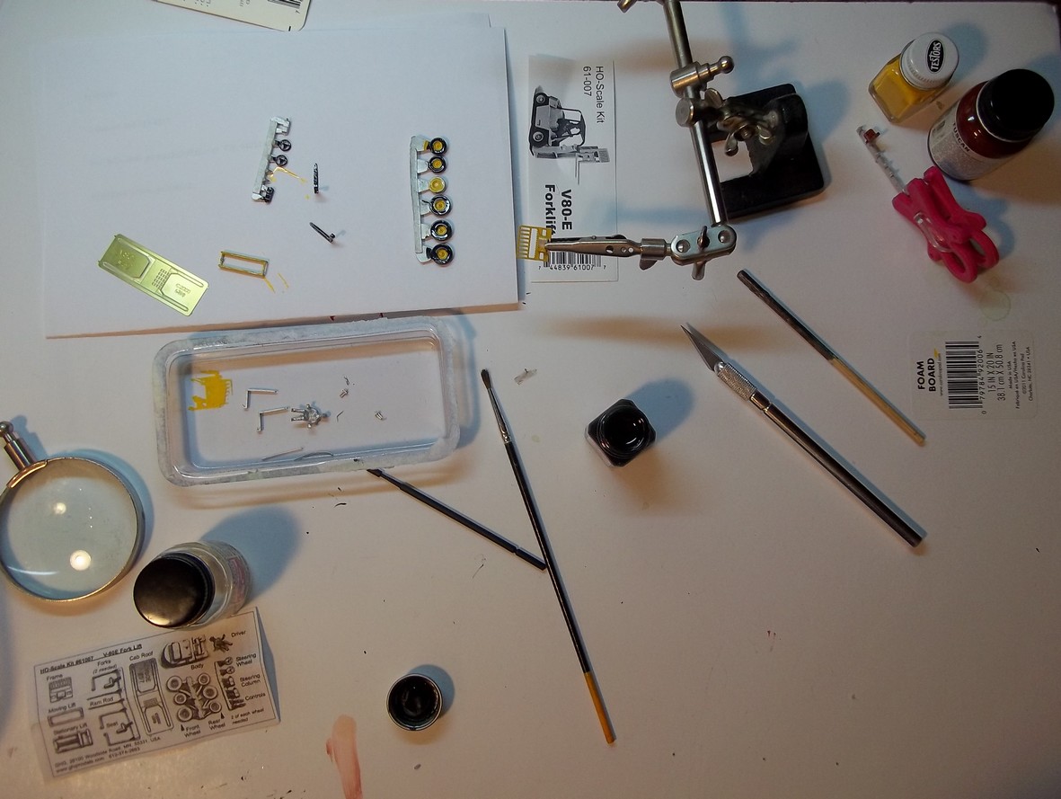
Before separating the white metal parts from the 'trees' the manufacture recommended that they be painted. A small brush and Testor's Black and yellow enamels did the job.
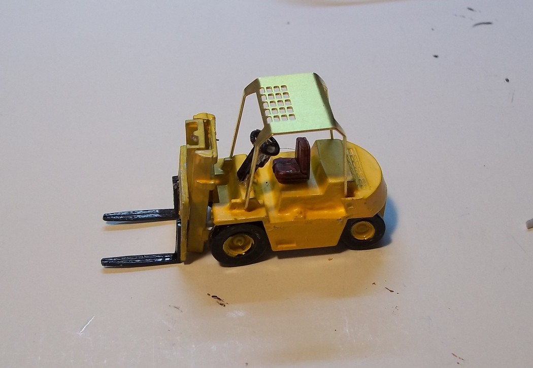
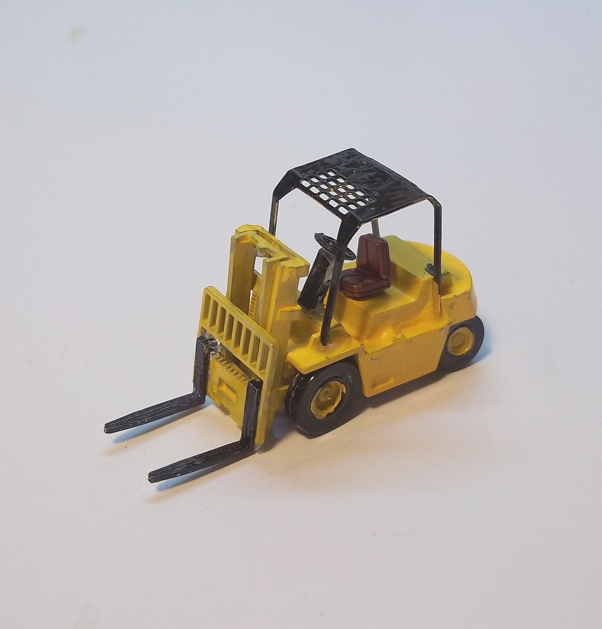
The finished forklift. Although small and sometimes tedious, I enjoyed the assemble of this little model. It will add a bit of character to the back yard of Shocker's Electric.
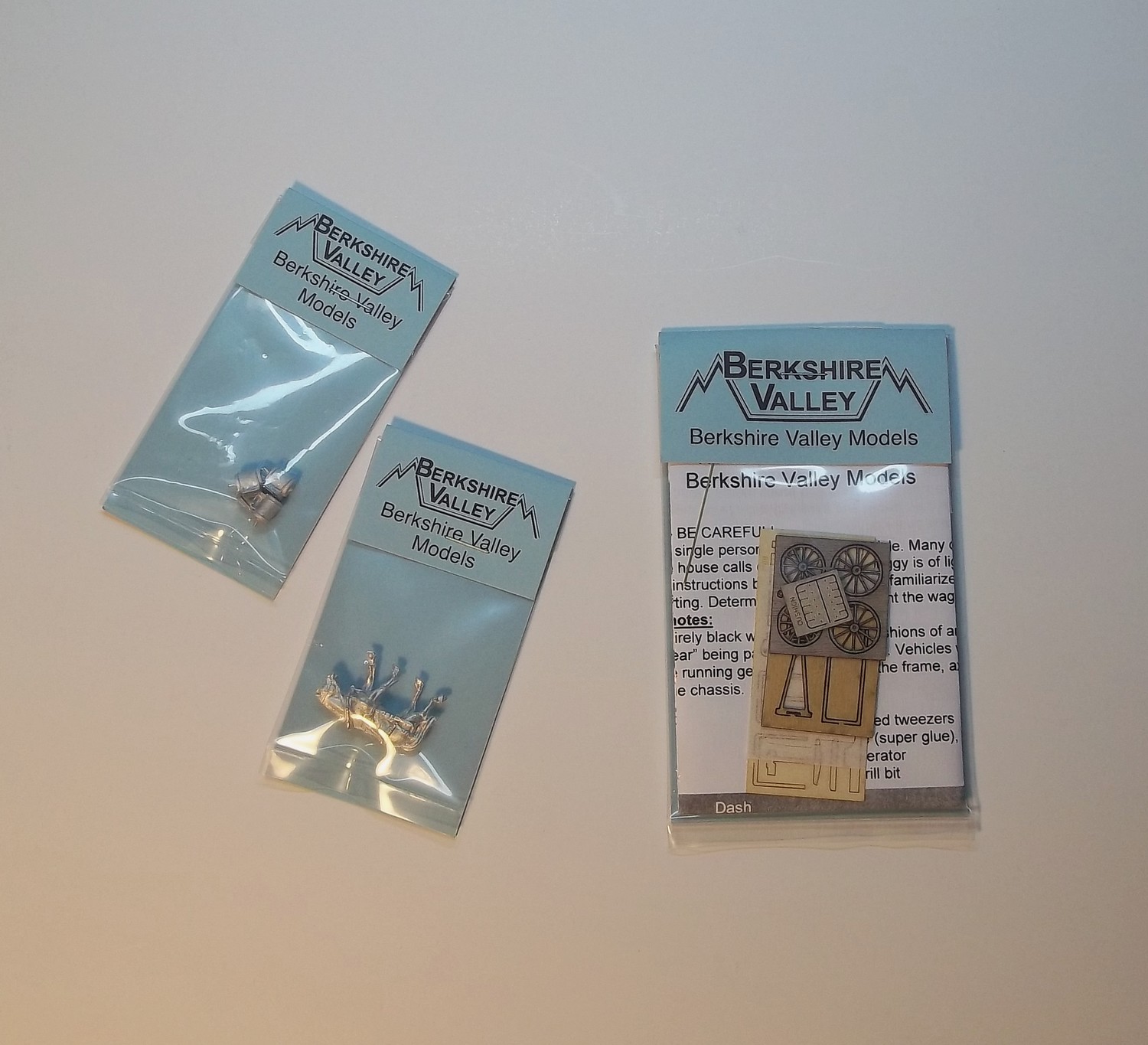
In a moment of weaknes I purchased an Amish Buggy Kit from Bershire Models. Building this kit was an exercise in frustration for me. To Start things off one of the buggy wheels managed to flip out while I was cutting it from the laser cut board.
An e-mail to Berkshire soon remedied the problem when a new set of buggy wheels arrived in the mail.

An e-mail to Berkshire soon remedied the problem when a new set of buggy wheels arrived in the mail.
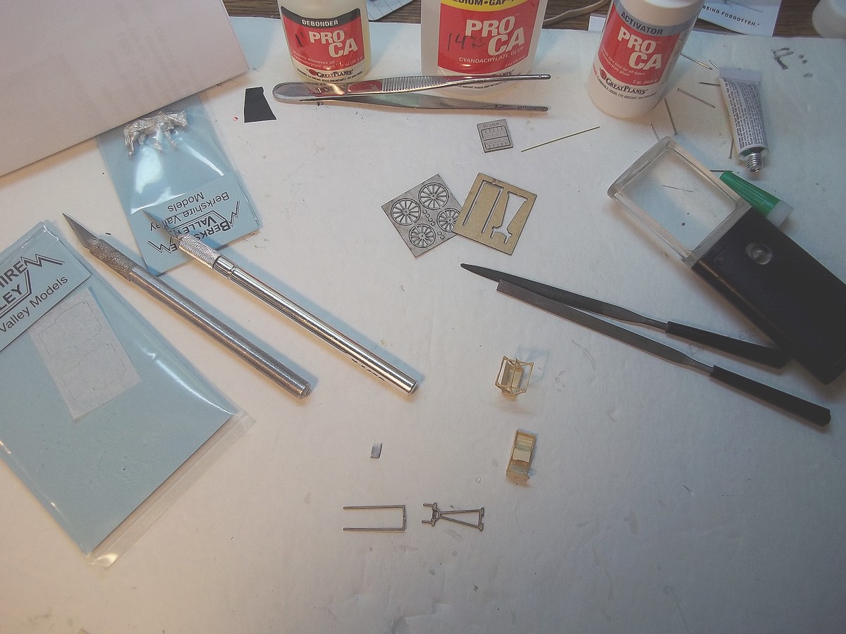
Construction of the buggy base and seat are underway. The small pieces gave me fits. I had to debond acouple of pieces and glue again to get the proper alignment.
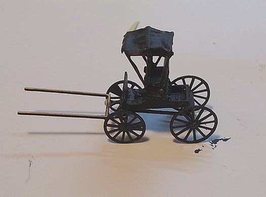
The Amish Buggy completed. Two thinned coates of Testor's black enamel were carefully applied to the buggy itself and even more carefully on the tissue paper hood.
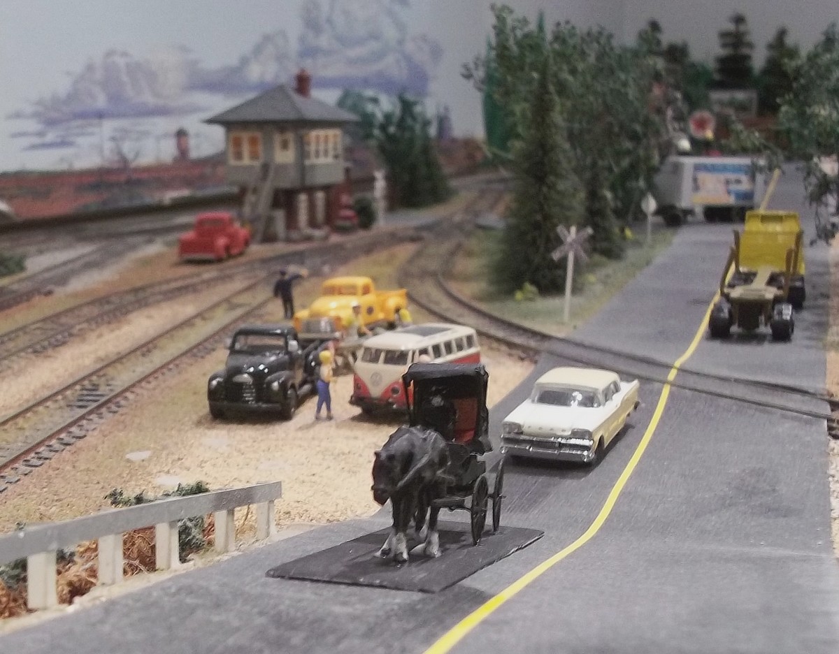
I painted the cast metal horse and driver with Testor's black enamel. A touch of white for the horse's hooves and the drivers shirt completed the project. The horse and buggy are located on the layout near the bottom of the incline to the highway overpass where they have acted as an obsticle for truck and auto traffic.
Structure and area lighting on the Black River Valley layout have becoume a problem. A hodpodge of wire and circuits that has become difficult to trouble shoot and maintain. I have decided to redo the system with a two circuit lighting buss under the layout.
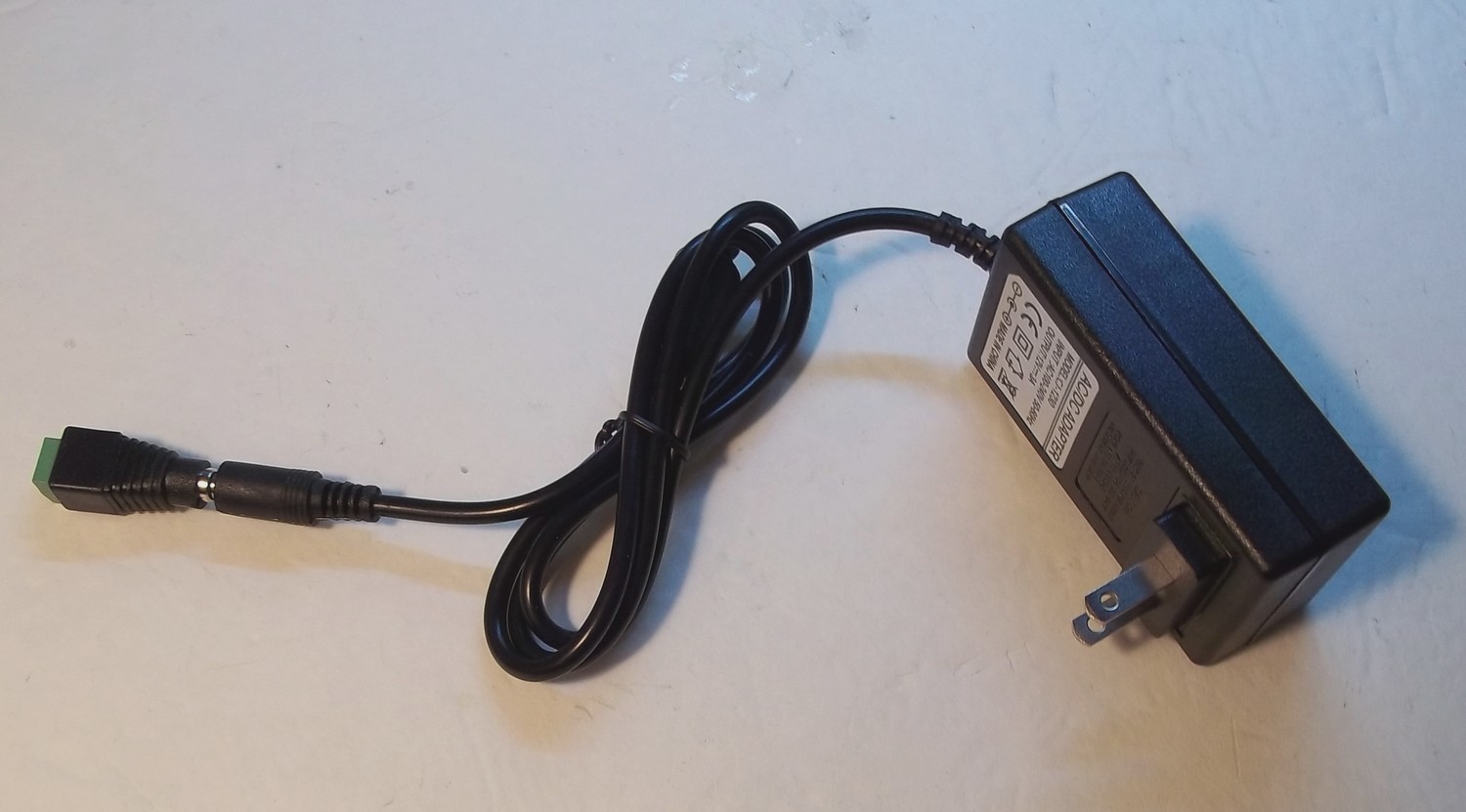
With the inability of the two MRC Raillpower transforms to carry the lighting load. This 12 volt, 3 amp wall wort power supply is the new power source for the new BRVRR struccture lighting buss. I installed it under the layout and split the output into two circuits controlled by push-button switches on the layout facia. Now that the lighting buss is complete and all of the structures and public lighting is in place, everything is working properly.
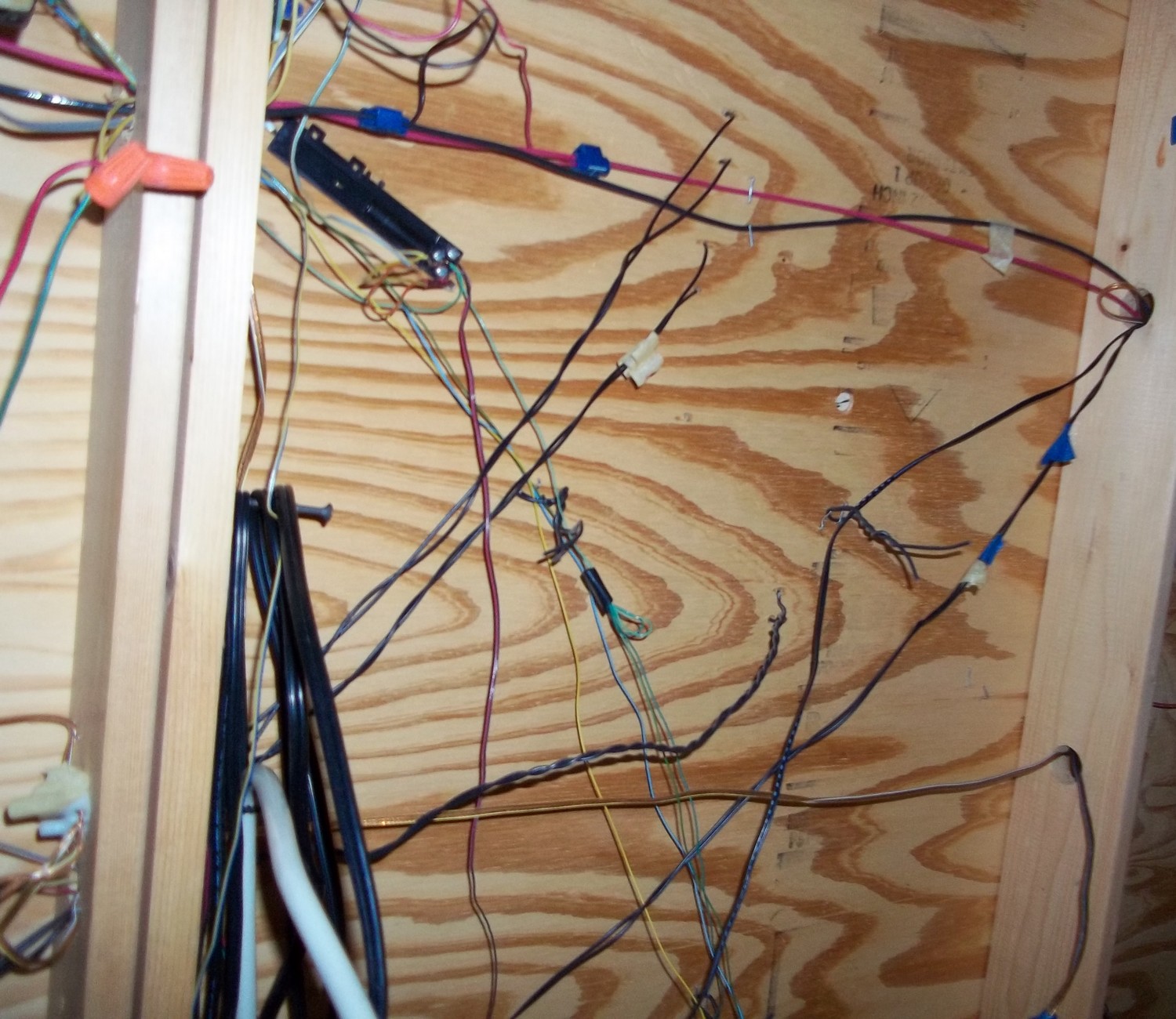
To illustrat my point: The photo at right shows a significant portion of the wiring under the layout. The red and black wires at top are the DCC power buss. The twisted black wires are part of the lighting circuts for the street lights and buildings. The light green/blue and yellow wires and some of the red/black wires are for the turnouts. The heavy cords at left are for the power supplies. An obvious mess.
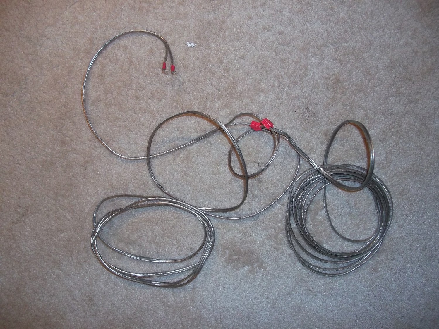
Because I had about 50-feet of it, I used 20-feet of standard speaker wire split in two more-or-less equal lengths. I connected them together with suitcase connectors to form my buss. Small bayonet condecters were used to connect to the power supply.
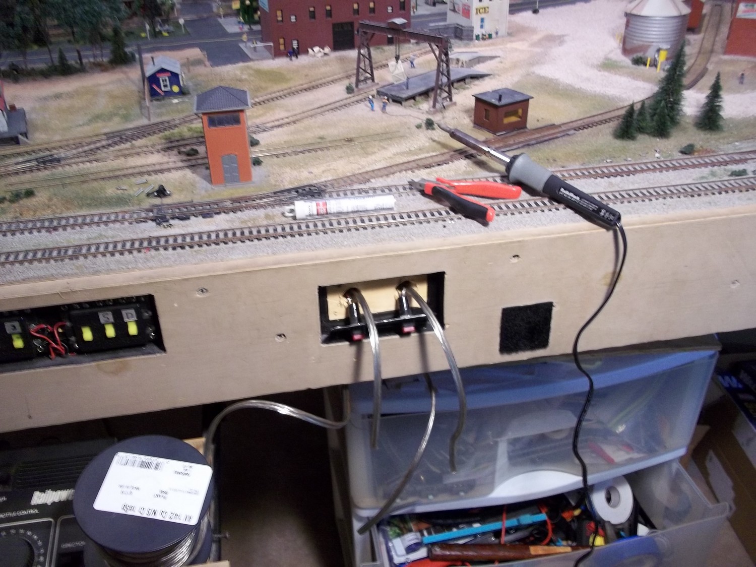
Here I am in the process of soldering the wires for each leg of the lighting buss to the switches that control each leg.
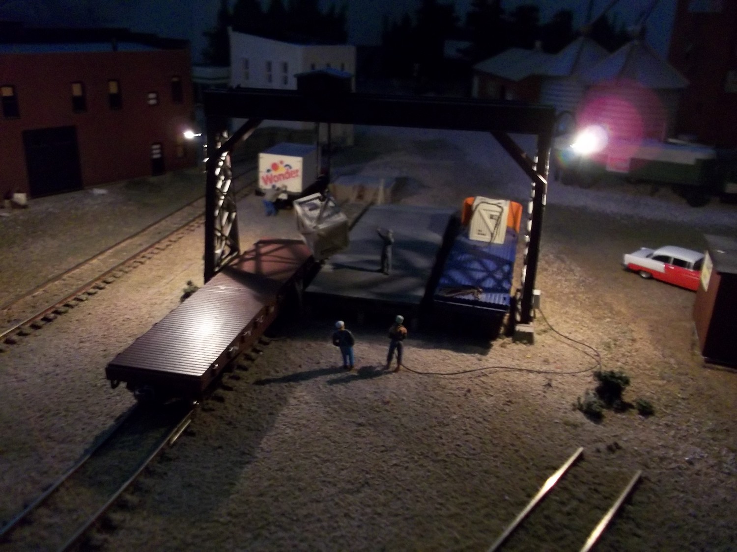
The first test of the 'right' half of the lighting buss. My team track scene is lighted again. I had similar success with the 'left' half of the buss. Five structures or areas working and many more to go. Its a start. Unfortuanately the layout is too low for me to sit up and make the necessar connectiona.Not easy to do as I have to lay on my back under the layout to make the connections. Even with a creeper I can just barely reach the wires. A few at a time will get it done, eventually.
After installing a couple more exterior light, one in the loading dock and one above the entrance door I managed to wire the lights into the lighing buss after considerable struggle with suitcase connectors that didn't work properly I finally got Shockers Electric to light up.
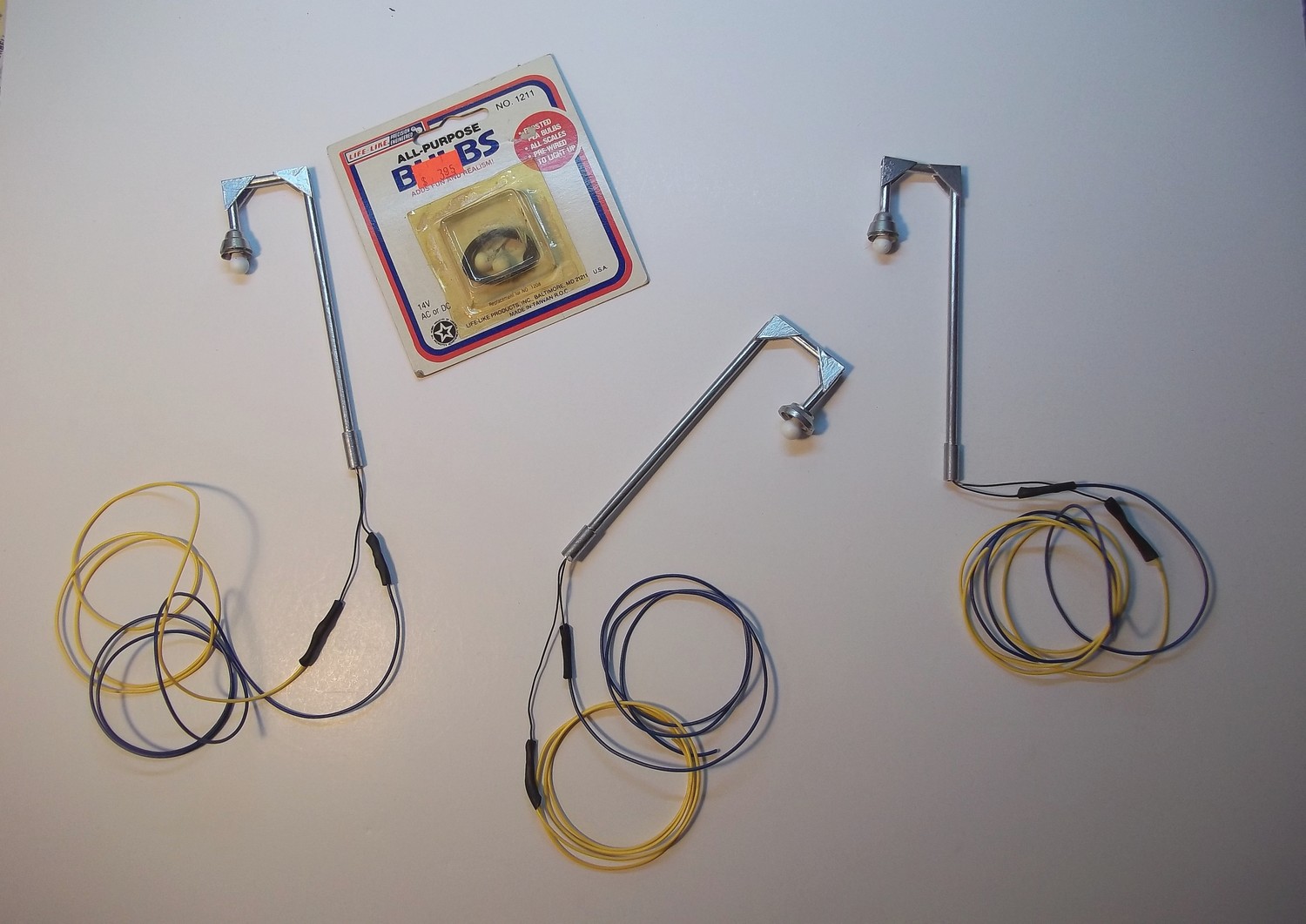
Here are a few of the light standards I made from a few pieces of 1/8 and 3/16-inch styrene tubing, small gussets of .010-inch styrene and grain of wheat bulbs purchased on E-Bay. the are intended to light some of the public areas of the layout including the rail yard, the work area around the engine house and Barron 's Oil Company lot.

One of the new light standards installed on the Barron's Oil Company yard and illuminated. I think the pole is a little too tall, but was disavowed of this opinion by people on the MRR Form. We'll see what happens as more lights are put into place on the layout.
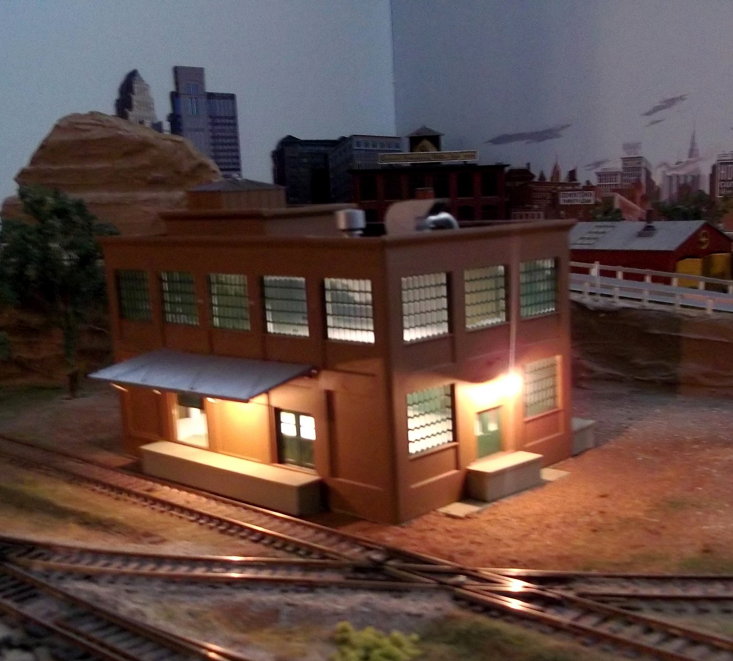
After the kit bash of the New Black River Station from Bachmann's Frankford Junction Depot Kit, I decided to tackle a rebuild/bash of the Redwing Flour Mill that has been on the layout for several years. I feel the structure is a little too large (tall) for its location on the layout. I decided to shorten it and repurpose it as an electrical supply/repair facility. Shockers.
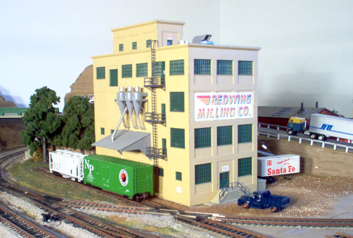
The starting Point. Walthers Redwing Flour Mill which has been on the layout since at least 2014 and perhaps before that. The kit was a Christmas gift from my daughter.
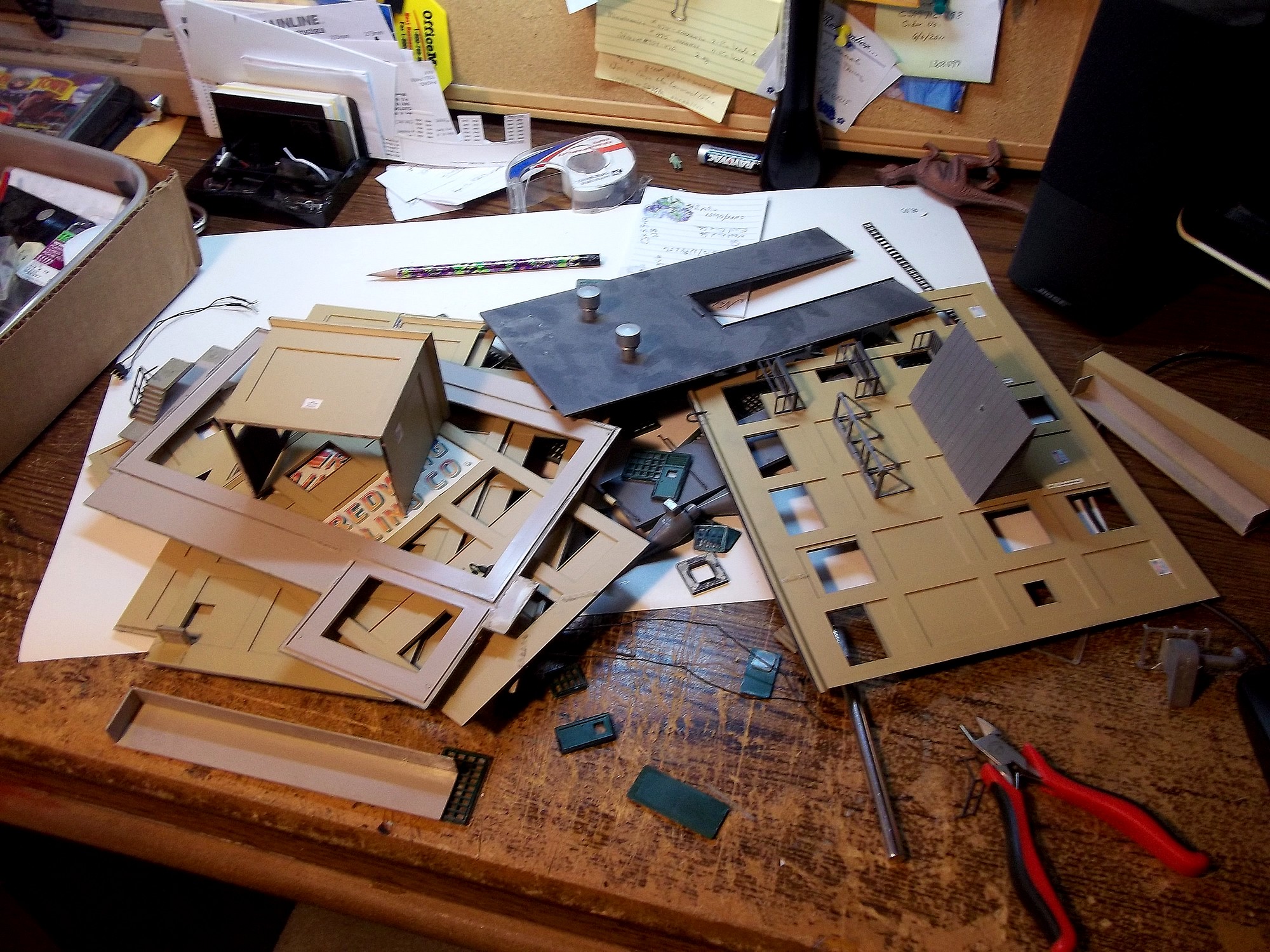
The flour mill disassembled and ready for modification. With my rotary tool I cut off one story of the structure and removed the crown molding from the upper facade. I shortende the front and back walls by one window section. I removed the boiler room from the rear and reduced the foundation plate and the roof panel to reflect the smaller building footpring. Joining the remaining parts of the and attaching the crow was a struggle. Lots of cutting and fitting.
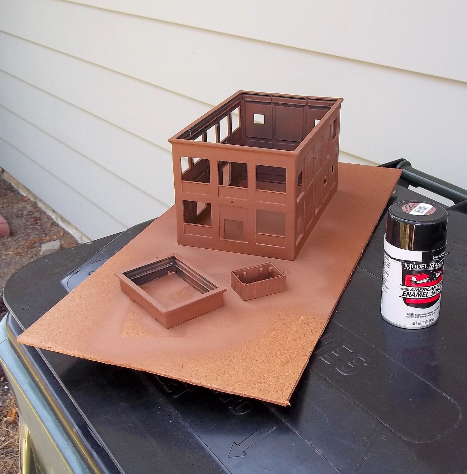
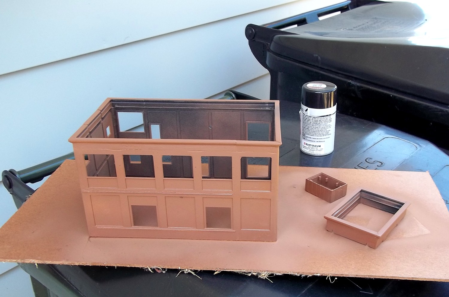
After gluing the wall pieces together they were painted with Model Masters 'Light Earth' No. 1954.
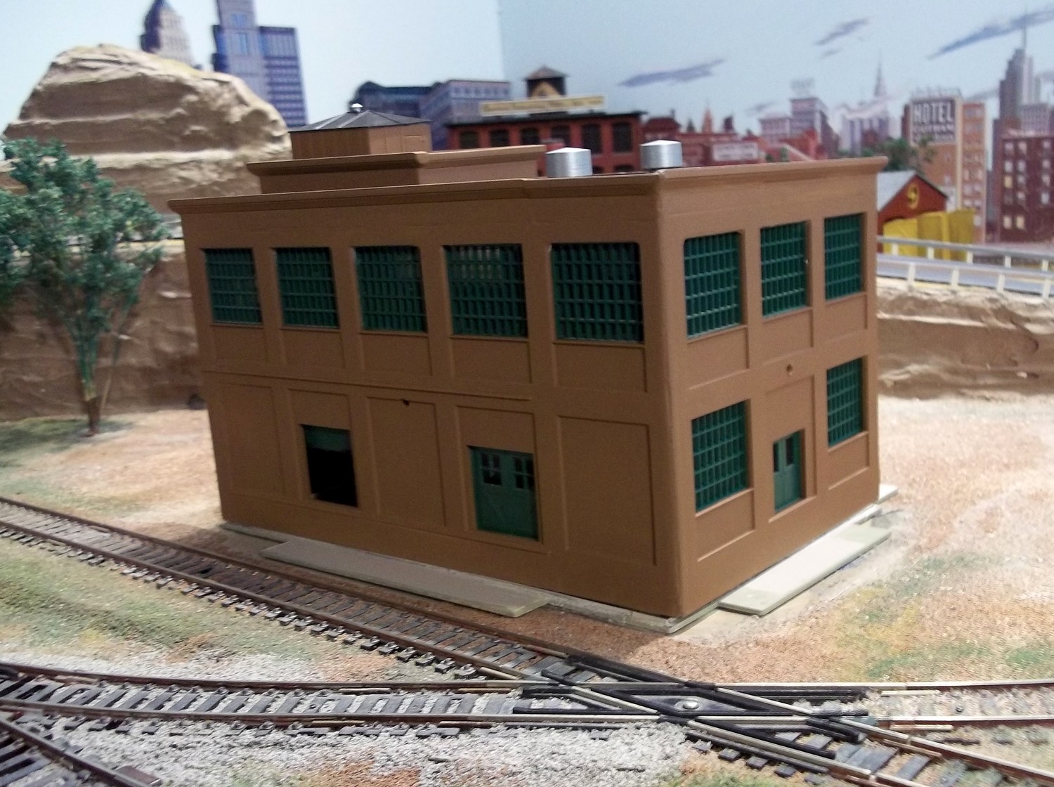
When the paint was dry I installed the original doors and windows. I did leave a loading door on the front partially open so there would be a glimps of the building interior. (Left thumbnail). Next came the loading docks, stairs and interior floors. The floors for the first and secod floor of the building were cut from foam board and located with four 1/4-inch square supports
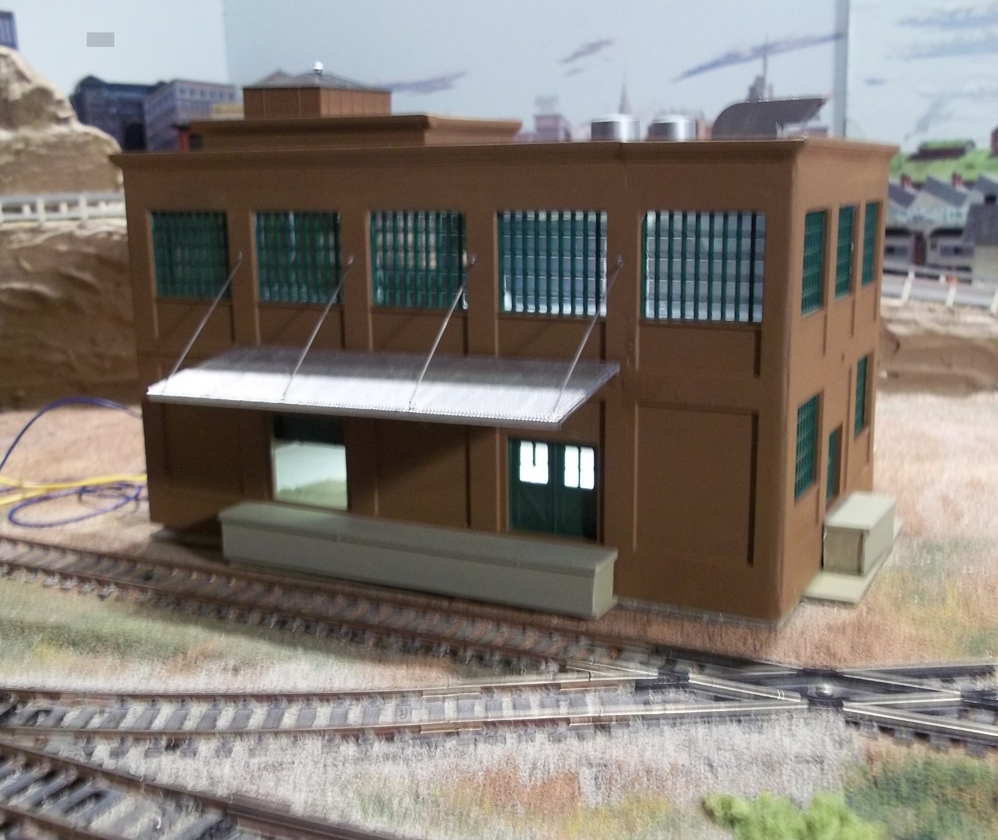
I fabricated wire supports for the loading dock roofs from .015-inch piano wire and installed them together with the corrigated roof panels ove the loading docks. The main roof panel snapped into place with no trouble. I flued the elevator houes and cupola into possition over the elevator shaft location.
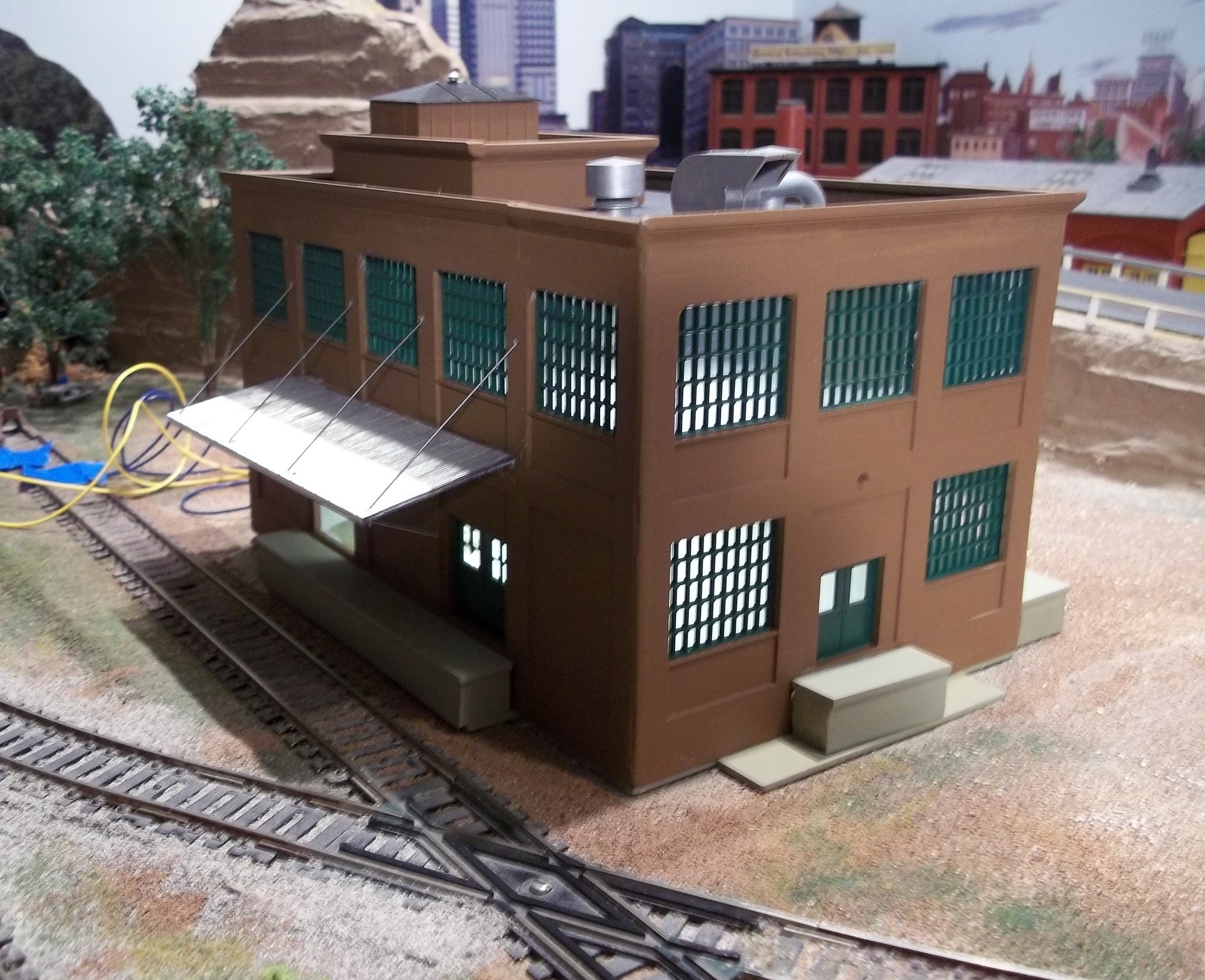

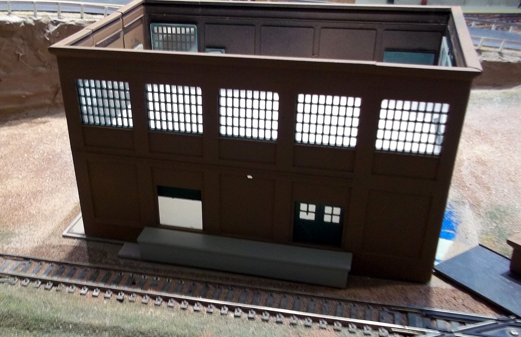
A strip of three white LEDs was securely afixed to the bottom of the second floor and another three light strip to the underside of the roof to provide interior lighting. At left the lights in daylight and at right at night.
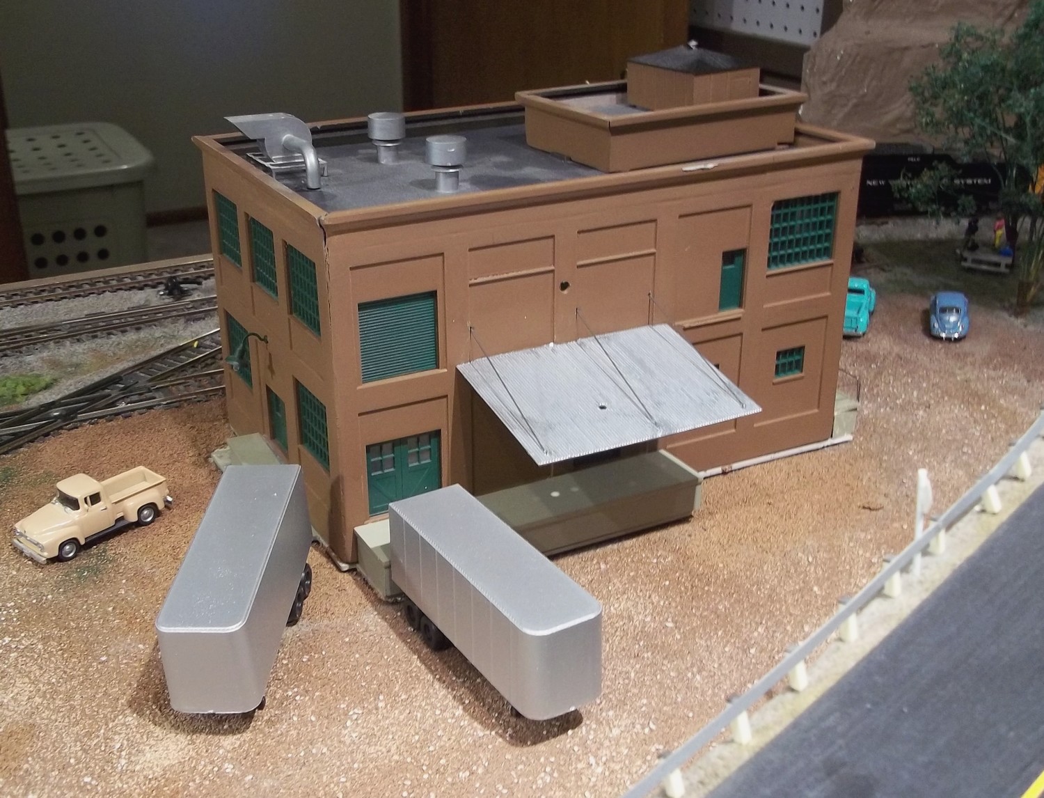
I added a few more details to the rear of the Shockers Electric structure. I added a roof/canopy over the small loading dock with wire supports. While I was at it, I replaced the LEDs on the upper floor with 6 new ones. The old ones had developed a flicker. I'm not sure why. More details are on order for the scene including more people, wire reels/spools, scale electric motors and a fork lift if I can find a suitable one with big tires. Signage is next.
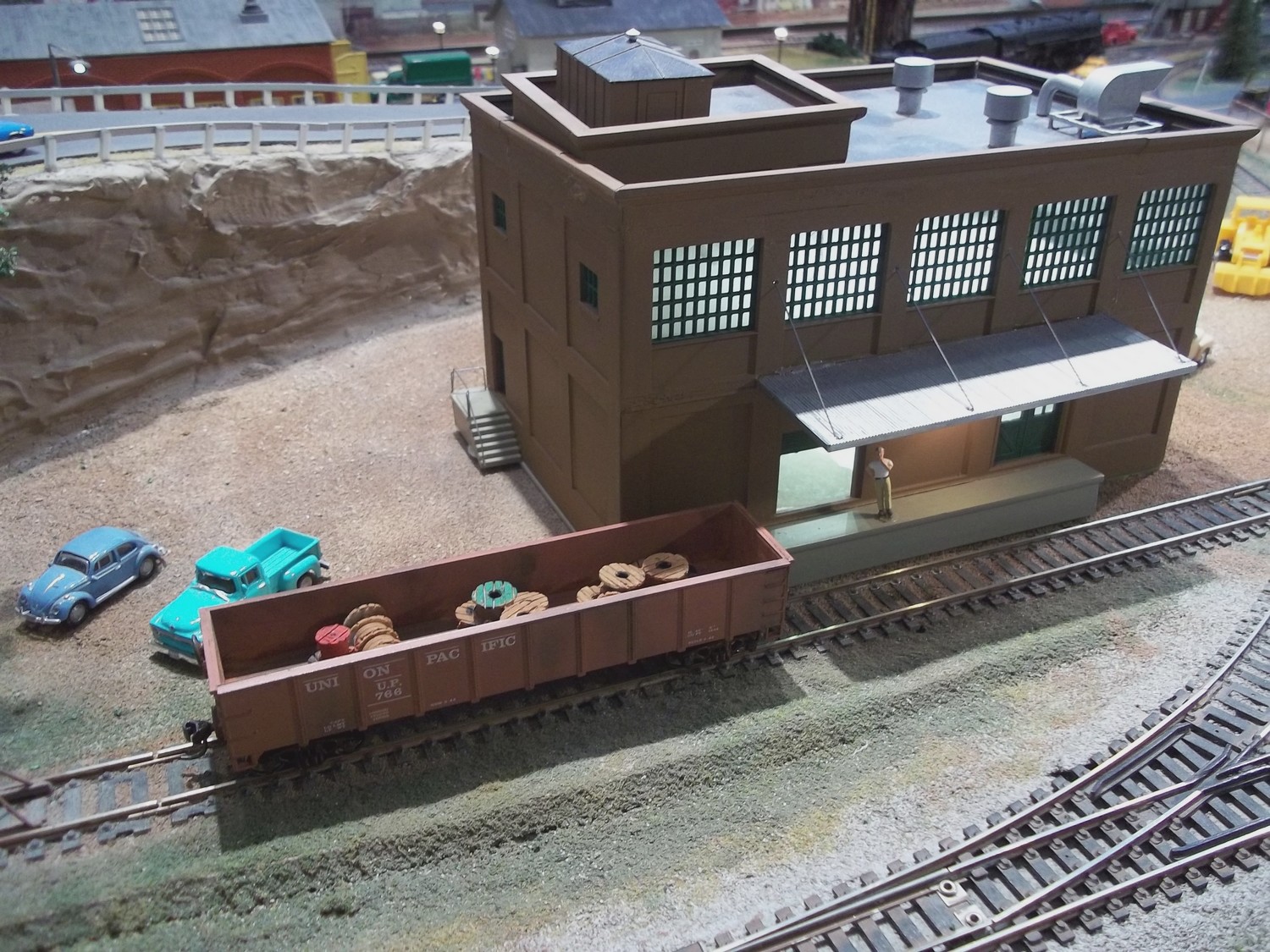
Some of the small parts I ordered for this project have finally arrived. Several scale wire reel were painted in various colors. I put them in an open gondola for the photograph. Eventually they will be located in various places around the Shocker's structure.
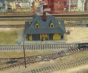
I have finished a project to replace the old Black River Station Depot building, an Atlas kit, with a larger structure which will have to be modified to fit the layout. Click on the thumbnail at left for updates on the project.
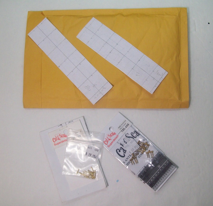
After numbering my Bachmann ALCO FA2 locomotive and its Walther's Trainline FA companion I decided to install the iconic 'train phone antennas' popular on the Pennsylvania Rail Road locomotives. While looking for something suitable for the antenna stanchions, I checked my parts bins for Athearn BB locomotive metal hand rail stanchions, which had proved viable in the past. No such luck. I shopped for very small cotter pins, no luck. I finally tracked down two sets of Cal-Scale PRR Antenna Stanchions at P.F. & S. Railway Supply in Pasco, Washington. Shown at left are the Stanchion kits and my locally generated drilling templates for the FA and FA2 locomotives. At right, some of the stanchions are in place on the FA2.
By 'clicking' on the thumbnail at right, you will see a short 'photo essay' on how I converted a Burlington E7 in Silver and Red livery to New York Central's gray cigar band livery.
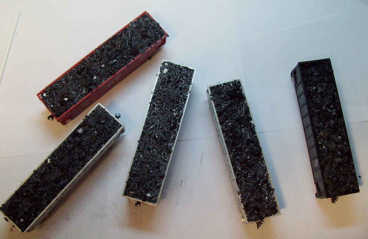
Hopper Project
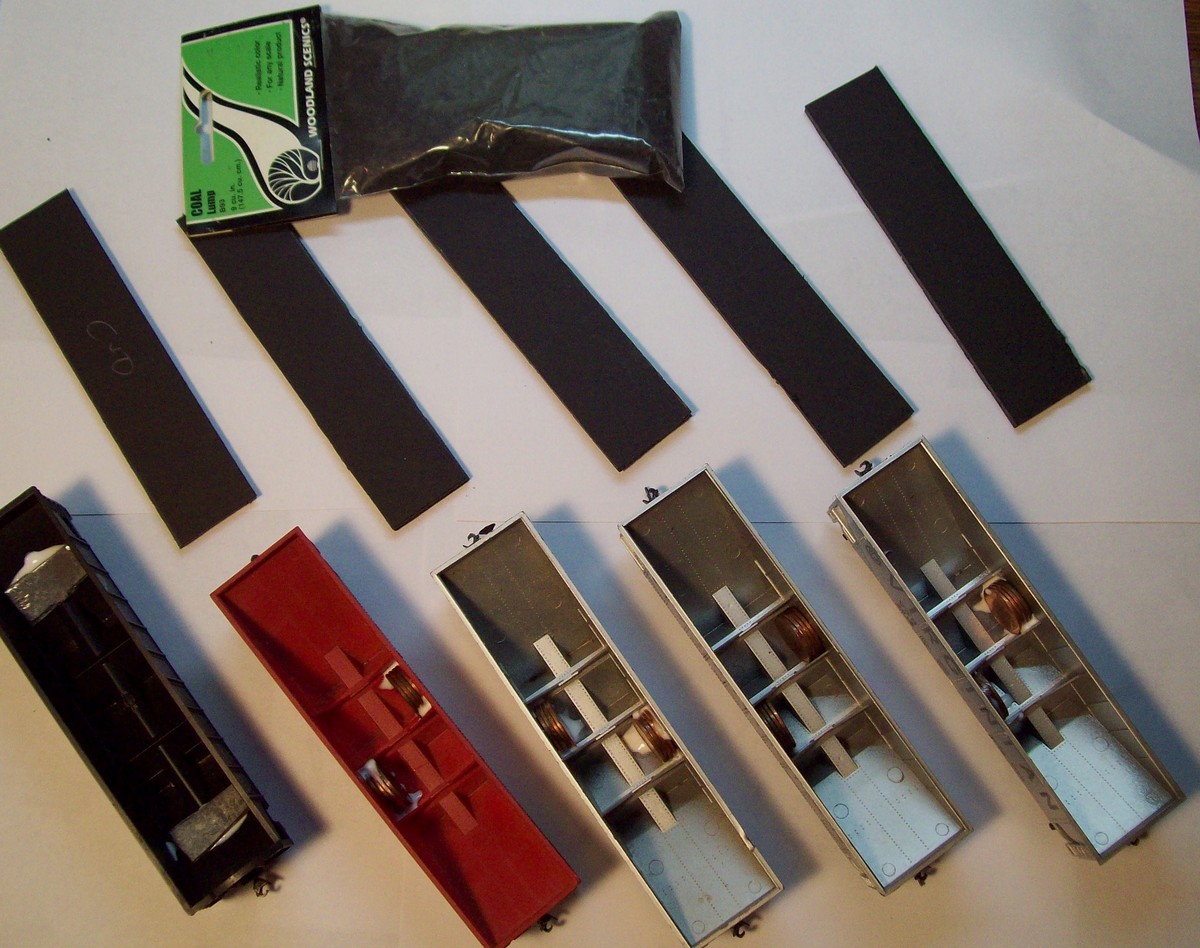
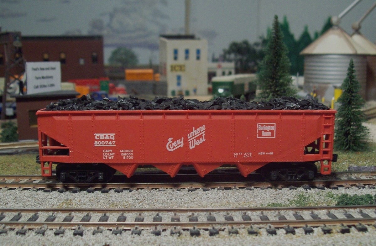
At left is a thumbnail of the foam board filler/foundation for the coal loads in the hoppers. At right is the thumbnail of the hoppers with their penny weights glued into place, the foam foundations and the Woodland Scenics lump coal for the loads. Left below is a thumnail of thecoal loads in the hoppers waiting for the deluted Elmer's white glue to dry. At right below is CB&Q hopper #800747 which is representative of all the hoppers in this small project.
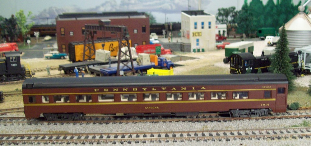
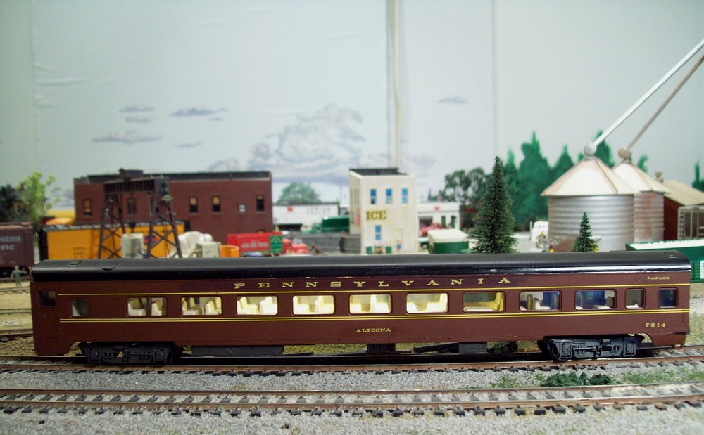
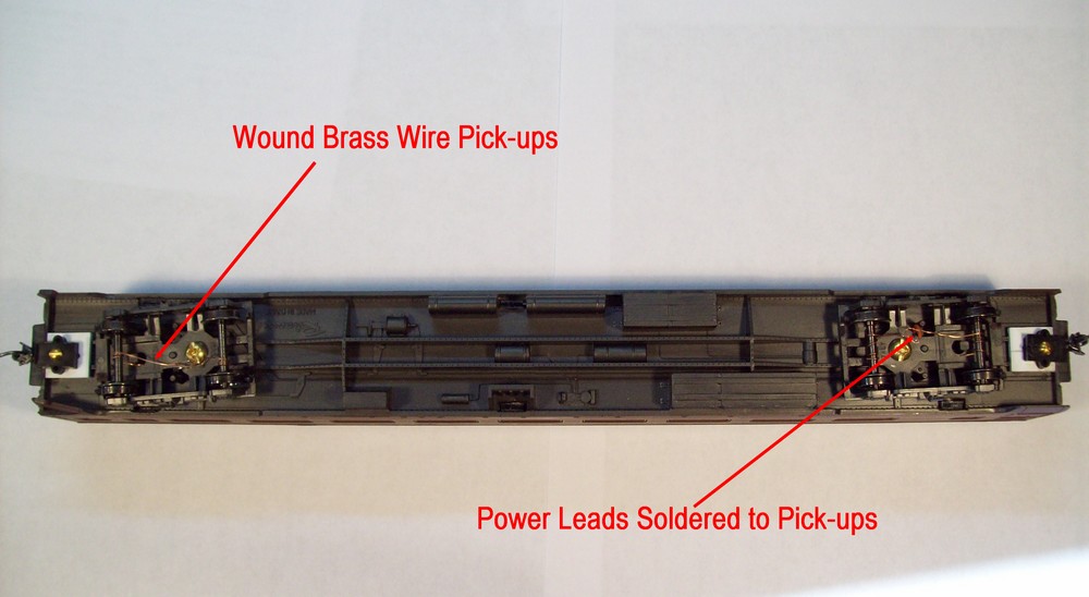
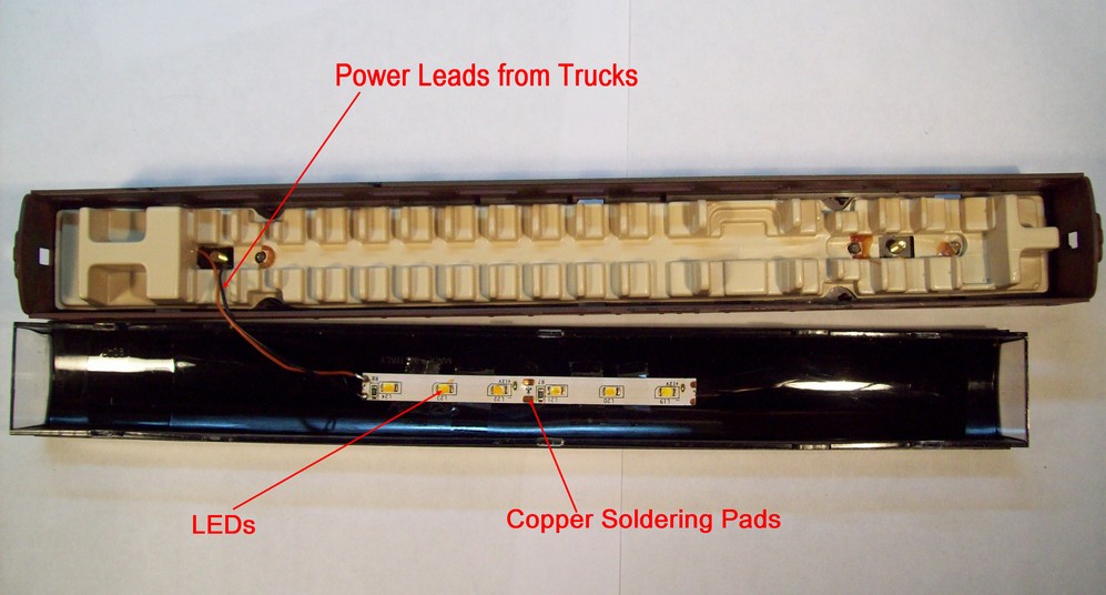
At left is a thumbnail of PRR Parlor Car "Altoona" as it was before lighting. At right is the same car with LED tape lighting installed. I used a strip of six lights powred from wound-wire pickups on the axles of both trucks. The LEDs do a good job of lighting up the interior of the car. The lower left thumbnail shows how the wound wire pickups were installed. Basically, I wound a brass wire around the axles and soldered a lead wire to them. The lead wire goes to the input on the strip lights. The lower right thumbnail shows how I installed the strip of 6 LEDs. The adheasive on the light tape isn't very strong so I augmented it with cellophane tape which works quite well. As can be seen in the photo at upper right, the light in the car is a bit uneven. I intend to split the LED lights into two pairs of 3 and spread them apart in the car. I'll let everyone know how it goes.
By 'clicking' on the thumbnail at right, you will see a short 'photo essay' on how I tinted the 'glass' in two of my Athearn BB streamlined Santa Fe dome cars. The process was suggested by a thread on the Model Railroader Forum. With a few modifications, my version is presented here.
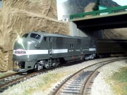
The thumbnail of the Pennsylvania E8 locomotives at right will lead to a short multi-image description on how they were made. Both units are Proto2000 models and both were in Atlantic Coast Line livery when they started out. I stripped, modified, painted, decaled and detailed both shells to make the locos you see in the thumbnail. Enjoy!
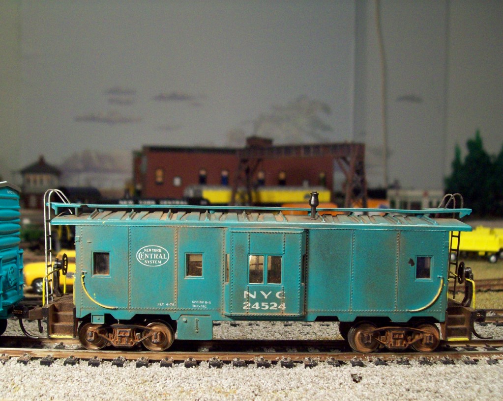
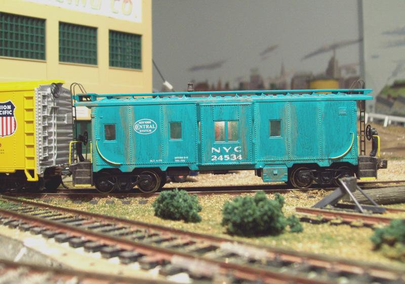
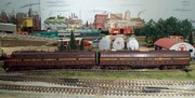
Both of these NYC wide vision cabooses (cabeese) were constructed from Athearn BB kits. I modified them a little by applying .005-inch clear styrene for window glazing and installing metal wheels. I then weathered them with washes of acrylic paint and Bragdon Enterprises weathering powders. I think I got a little carried away with #24524. Then I lightly touched the grab irons, hand rails and steps with yellow paint to add some highlights. For a larger image push the thumbnail of your choice.
Because I've always wanted to do it, I fabricated and installed interior lighting on both cars. I used a simple wound brass wire pick-up system for #24524 and a modified Kadee coupler-spring pick-up for #24534.
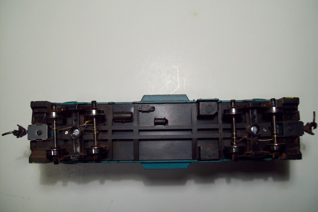
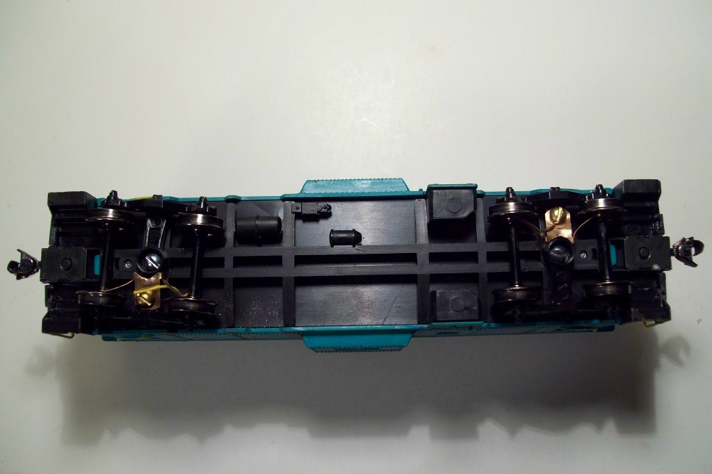
To make the wound brass wire pick-up I used on Caboose #24524, shown at left, I just wound .010-inch brass wire around the metal axles on each truck. Then I soldered a length of thin decoder wire to the pick-up and threaded it through a 1/16-inch hole I drilled through the bottom of the chassis and weight. After doing the same for the other truck, I soldered a Model Power #381 12-16 volt, .03 amp bulb to the leads. I left the leads a little long so I could tape the bulb to the roof of the caboose body. To ensure good electrical contact, I added 1 1/2-ounces of lead weights over each truck. After installing Kadee #5 couplers and snapping the body onto the chassis, my caboose was completed. 'Click' the thumbnail at left for a larger image.
I didn't have another set of metal axle wheels for Caboose #24534 so I used a slightly modified Kadee coupler spring for a pick-up with the Proto wheel set already in place. To make an electrical pick-up that would brush the inside of the wheels, I bent the coupler spring tabs out away from the spring base to form the pick-up 'brushes'. Then I drilled and tapped a hole for a #2 screw through the cross member on the truck. After trimming the edges of the spring/pick-up to fit without interfering with the bolster, I attached a length of decoder wire to the pick-up and cross member with a 1/4-inch long #2 screw. 'Click' the thumbnail at right for a larger image. After attaching the wire, assembly followed the same steps as I used with the wrapped-wire pick-up.
Both methods of electrical pick-up work well. The cabooses track well and I haven't had any trouble with binding. The lights stay illuminated with very little flicker so I consider the project(s) a success.
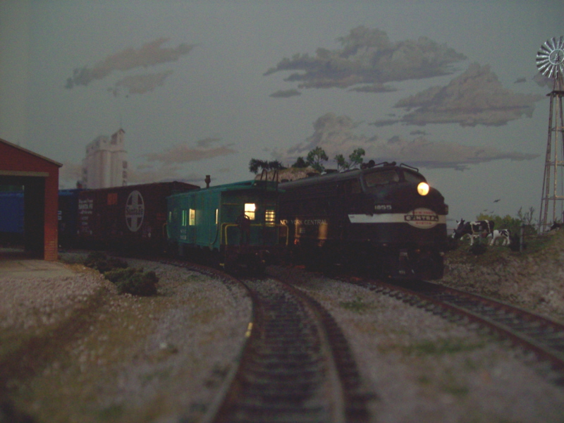
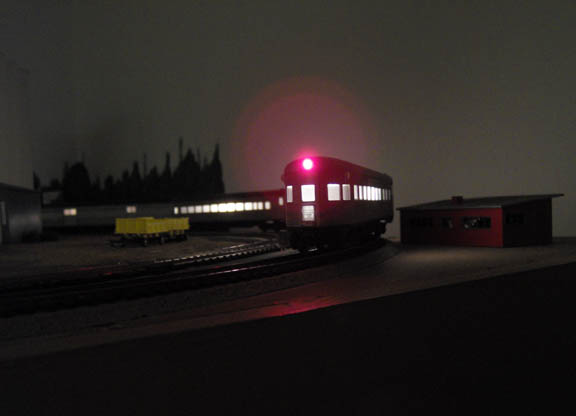
Here is a picture of NYC Caboose #24524 as it rounds the curve near the Farmers Union elevator. NYC F7A #1855 pass on the outer main line. In the near darkness that the photo was taken in, the interior lighting in the caboose looks pretty good. Push on the thumbnail at right for a larger image.
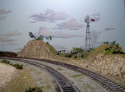
I filled in an empty corner of the Black River Valley layout with a Pasture scene to brighten up the layout a bit. I really hate to do scenery, but this little project wasn't too much of a chore. Sculptamold made the hard part of the job easy. Click on the thumbnail at left to view a short 'photo essay' on how I did the job.
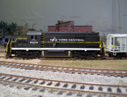
During January of 2009, I installed a Soundtraxx DSD-101LC sound decoder and two 3/4-inch speakers in my Atlas Trainman RS-32, NYC #8038. The installation was more complex than most and took some 'engineering' to get right. If you click on the thumbnail at right, it will take you to a short 'photo essay' on how I did the installation. The basic steps are the same for virtually all locomotives not built for sound/speaker installations. Check it out. It may help you sometime in the future. Note: I modified the speaker installation a little. New photo added.
After I installed a Soundtraxx DSD-101-LC decoder in my Santa Fe FP-45 #5941 a few months ago, I was so pleased with it that
I began looking for another FP-45 to pair it with. Unfortunately, after several train shows with no luck finding one in Santa Fe
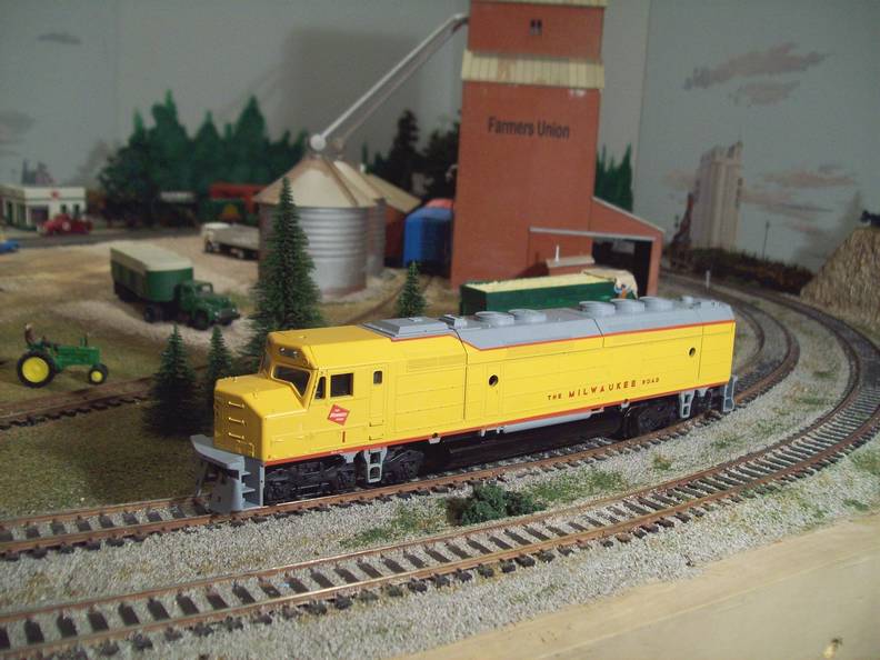
Warbonnet livery, I decided to make my own. I purchased the Athearn BB FP-45 in Milwaukee Road livery shown at left above. After
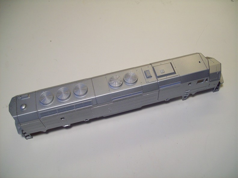
stripping the paint and cleaning up the shell, I sprayed on a coat of Floquil silver as a primer. Photo at right, above. For the
red paint, I made a mask out of 'Scotch Tape' and sprayed on a couple of coats of Floquil, Santa Fe red with my trusty Badger air
brush.
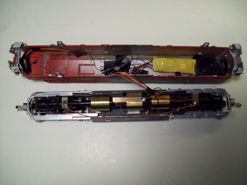
After the paint had dried for a day, I applied the striping, lettering and numbers from Microscale Decal sheet No. 87-599 and finished with a coat of Dull Cote to seal everything. I made the door handrails from some .015-inch steel wire I had on hand and installed the handrails supplied with the kit at the front and rear. Next, I brush painted the trucks and frame silver with Testor's enamel. When the paint had dried I installed two Model Power 12-16 volt, .03-Amp incandescent bulbs, in custom holders made from styrene tubing for head and backup lights. Lastly, I installed a Soundtraxx DSD-100LC sound decoder and a 1-inch Soundtraxx speaker and enclosure. The thumbnail at right shows the FP-45s innards.
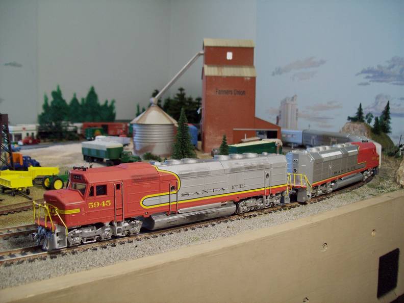
I applied Details West MU hoses and Kato air hoses to the front and rear of the locomotive. I weathered the loco with thinned acrylic browns and some black and several layers of Bragdon Enterprises' adhesive powers. I hand painted the door handrails silver and the front and rear handrails with Testor's yellow. A final coat of Dull Cote sealed the surfaces. The installation of Kadee couplers, front and rear, finished my model. The thumbnail at right shows my new SF FP-45 on the lead as it rounds the curve near the Farmers Union grain elevator on the West End of the BRVRR layout. It runs and sounds as good as its brother! I am quite pleased with the results
In 2006, I modified an Athearn BB streamlined baggage car so that it more closely resembled the cars used by the New York Central on its named trains. Inspired by a thread on the Model Railroader Forum and an inability to purchase suitable cars, decided to continue the modification of my streamlined passenger car consist over the last few weeks of February 2007. The thumbnail of the Observation Car at left will take you to a photo essay of the now modified cars and a brief description of what was done to achieve the desired results.
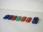
The Black River Valley Railroad has highways, streets and parking lots that need vehicles to make them appear 'real'. With detailed scale cars costing a king's ransom I decided to raise the level of detailing on several low-end, read cheap, Life-Like autos to make them more 'respectable'. My intent was not to make them rival the better scale cars, but to make them 'good enough' at a viewing distance of 3-feet. Push the thumbnail at right to see a 'photo essay' of the steps and procedures I followed in an attempt to meet my goal.
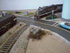
After long deliberation, I decided to install new crossing signals and automatic flashers on the double-track railroad crossing near the BRVRR COOP. I used an infra-red system because I wanted the signals to operate in the dark. I settled on Berkshire Junction Infrared Deluxe Crossbucks. They seemed to be the best bargain and the most versatile. This 'photo essay' shows most of the steps I took during the installation. I'm sure the general procedure would apply to any stand alone crossing control system currently on the market. When you 'click' on the thumbnail at right, a new window will open with a series of step-by-step photographs and text decriptions.
This 'essay' is in response to several questions I have received via E-Mail. When I expanded the BRVRR to 4' x 8' and then 4' x 10' I wanted to install Under-Table switch machines on the turnouts/switches for the cross-overs, return loop, yard and engine facility. The change over would get rid of the unsightly Atlas surface mount switch machines and allow for a more compact arrangement of track. Most of the powered turnouts were out of easy reach or had to be operated in pairs. With 12-turnouts/switches to convert I was facing a considerable expenditure. I considered Tortise machines, but they were out of reach finacially at the time. There had to be a way. The photo at right illustrates how I solved the problem. If you 'click' on the thumbnail, a new window will open with a short photo-essay an how I converted my Standard Atlas Switch Machines to Under-Table Machines.
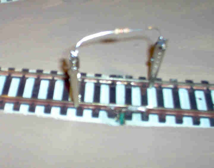
When I installed my first Lenz Decoder in BRVRR EMD F7A #1116, I had a devil of a time programming it with my Digitrax Zephyr command station. After a dozen or more tries I looked for help. I found it on the Atlas DCC Forum. I described my problem in a post on the forum. Within an hour I had the answer. Apparently Digitrax command stations put out a very low voltage/amperage to the programming track. To fool the command station into increasing the voltage/amperage Digitrax recommends placing a 1000 Ohm resistor across the programming tracks to increase the load.
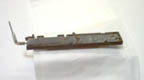
I soldered an alligator clip to each side of a 1/4 watt, 1000 Ohm resistor and clipped it to my programming track. Viola! The Lenz LE1000W decoder immediately responded to my Zephyr. Ever since, I have always clipped my little resistor to the programming track when dealing with a Lenz/Atlas decoder. The thumbnail at left and the larger photograph it leads to, show the resistor in place on the programming track. It is not the clearest photograph I ever made, but it should get the point across.
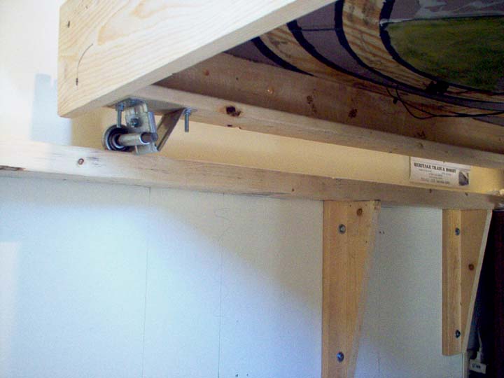
I have had several questions about how I used garage door rollers to support my layout. The photo at right should illustrate the point without too many words. There is presently one roller at each corner of the layout. I used 2" x 4s" for 'rails' because that is what I had on hand. I routered a groove into the top of each one to serve as my roller track. It works quite well, but if I had it to do over again, I would use small aluminum channel for the track instead. I am thinking of adding a third, center, roller to each end for additonal support. Hope this helps!